Flat Rate for NB-IoT: Accessing the 1NCE Management API

Background

1NCE is an IoT connectivity provider with a disruptive pricing model:
The company offers a so-called “IoT Flat Rate”:
For 10 € you get a SIM card with 10 years lifetime and a flat rate traffic volume of 500 MB and 250 SMS.

As a maker of IoT devices communicating using NB-IoT you now question yourself:

  • Would such a flat rate be sufficient for my use-case?
  • What is the current traffic consumption of my device?
  • What effects does it have on the traffic consumption if I change the communication pattern in one or the other way?

Altough some RF modules like the Quectel BG96 offer counters to query the number of bytes sent and received, which already give a good indication about the traffic consumption, these perhaps don’t take into account the traffic on the lower levels of the communication stack, like UDP or TCP.

So why not directly ask 1NCE for the “consumed” traffic volume?

1NCE offers an Application Programming Interface that allows users to implement the most important functions of the Customer Portal into a customer’s environment. The supported functions of the 1NCE API generally enables the customer to manage, control and monitor the 1NCE SIM Cards from an external system.

https://1nce.com/en/help-center/tutorials-documentations/api-functionality/

For example, one can query for a list of SIM cards using a HTTP GET request to

https://api.1nce.com/management-api/v1/sims

… or get information about the left over flat rate traffic volume with a HTTP GET request to

https://api.1nce.com/management-api/v1/sims/my-iccid/quota/data

There is a Swagger UI interface at https://api.1nce.com/management-api/swagger-ui.html that lets you play around with the functionality of the Management API.

This example application connects to this Management API, gets the SIM cards and
creates a Round-Robin-Database (RRDB) out of that. Then, the application queries the current traffic consumptions of the cards and enters it as sample into the RRDB.

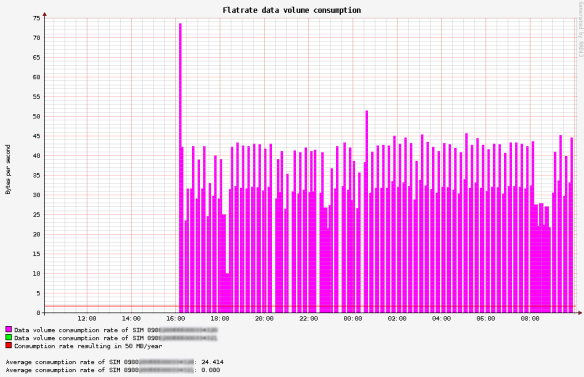
And, as the final goodie, if you navigate to port 8080 with your web browser, a nice graph with the consumption rate of the last 24 hours is displayed.

flatrate-data-consumption

How to configure

Find the source code on github at https://github.com/wklenk/1nce-management-api-access-and-rrd4j-graphs

Put your client-id and client-credentials in configuration file application.yml:

ok-http-client:
# proxy:
# host: localhost
# port: 3128

1nce:
client-id: your-client-id
client-secret: your-client-secret
token-endpoint: https://portal.1nce.com/management-api/oauth/token

How to build

You need maven and a Java JDK to compile:

$ mvn clean package

How to run

$ java -jar target/1nce-management-api-access-and-rrd4j-graphs-0.0.1-SNAPSHOT.jar

On the first start, you may see something like this:

...
Tomcat started on port(s): 8080 (http) with context path ''
route=Route{/a.b.c.d:xxxx} response=Response{protocol=http/1.1, code=401, message=, url=https://portal.1nce.com/management-api/v1/sims?page=1&pageSize=100}
Request did NOT use an Authorization header.
Requesting a new Access Token by client credentials
Token endpoint returned status 200 OK and tokens OnceAccessTokenService.Tokens(accessToken=206bed3b-11e6-4253-97c4-cb410f6f08ab, tokenType=bearer, expiresIn=3560, scope=all, appToken=eyJhbGc...)
QuotaDataResponse(volume=488.29297, totalVolume=500.0, expiryDate=2028-11-20 00:00:00, lastStatusChangeDate=2018-08-20 11:25:03)
QuotaDataResponse(volume=499.98907, totalVolume=500.0, expiryDate=2028-11-20 00:00:00, lastStatusChangeDate=2018-08-20 11:25:03)
sample=update "./data-traffic-consumption.rrd" 1573889068:1.2275710689279974E7:11460.935679972172

If a RRDB file with name data-traffic-consumption.rrd already exist in the current directory, then it won’t be overriden.
If you explicitly want to start with a new RRDB file, start the application with option –override.

Fun fact: To meet the goal of 500 MB in 10 years, the traffic consumtion rate needs not to exceed the red line at 1.66 bytes/second. So, there is still much to optimize in the communication patterns of this example device.


NB-IoT Explorer

Explore Narrowband IoT (NB-IoT) Radio Networks in a comfortable, user-friendly way.

Animated picture

In this project, two extremely powerful components come together:

The Espruino Pixl.js with its built-in JavaScript interpreter is easy to program. The (native) Espruino Web IDE lets you transfer the code to the device using Bluetooth LE, so there isn’t even a USB cable needed to connect the computer with the device. The Espruino Pixl.js device has a large LCD display with 128×64 pixels, and four buttons on each corner of the display allow highly interactive applications.

The Quectel BG96 module module on the NB-IoT Shield provides multi-band support, so it can be used in many different radio networks all around the world. The NB-IoT Shield provides direct access to the serial interface of the BG96 module, so you also can try things out using a FTDI cable, which can be useful if you want to do firmware updates. The BG96 module provides a wide range of AT commands for a lot of purposes, and even provides high-level protocol implementations like HTTPS and MQTT, which can be very useful for IoT applications. Additionally, it provides geo-positioning by its embedded GNSS chip.

Material

  • Espruino Pixl.js – Bluetooth microcontroller programmable in JavaScript with built-in LCD display and Arduino footprint.
  • Dragino Nb-IoT Shield QG96 – Arduino shield that hosts a Quectel BG96 module. This module supports multiple bands for NB-IoT. Except NB-IoT, It also support LTE Cat M1 and EGPRS.
  • A SIM card from a network provider supporting NB-IoT.
  • Micro USB cable for power supply
  • Optional: GNSS Active Patch Antenna
  • Bluetooth Low Energy Dongle for your computer, if it not already supports BLE natively.

Preparation

  • Get yourself familiar how to connect the (native) Espruino Web IDE with the Espruino Pixel.js board via Bluetooth LE.
  • Play around with the code examples for the Pixl.js.
  • The 5v pin on the on the Pixl.js will be used to power the NB-IoT shield. There is a solder jumper near the LCD connector labelled “3.3 5V Vin”. Short Vin to 5v – the 5v pin will be connected to 5v (when connected via USB) or whatever the voltage provided on Vin is. Read more about shield power at https://www.espruino.com/Pixl.js#shield-power. (Using the 3.3v at the output of the power regulator does not provide enough power when the BG96 starts to transmit).
  • If you are good in soldering, you can consider to physically remove the big square socket connector at the reverse side of the NB-IoT shield, because it is in the way when the Pixl.js and NB-IoT shield are connected.
  • Connect the Pixl.js with the NB-IoT shield by its Arduino connectors.
  • Optionally: Attach the GNSS Patch Antenna.
  • Get yourself a SIM card suitable for NB-IoT and insert it into the SIM card holder of the NB-IoT shield. Note: The cut corner of the SIM card has to point in your direction when inserting it. If you don’t take attention, then there is a chance that you insert the SIM card in the wrong orientation.
  • Load the JavaScript code from https://github.com/wklenk/nb-iot-explorer into the (native) Espruino Web IDE.
  • Check for the JSON structure named connection_options and provide the appropriate settings for the NB-IoT network provider of your choice.var connection_options = { band: “B8”, apn: “iot.1nce.net”, operator: “26201” };
  • Turn on Minification in Settings -> Minification. Choose Closure (online) – Simple optimizations.
  • Send the application to the Pixl.js.
  • If you want to keep the application in the Pixel.js even after re-booting the Pixl.js, then save it to flash by typingsave();
     ____                 _
    |  __|___ ___ ___ _ _|_|___ ___
    |  __|_ -| . |  _| | | |   | . |
    |____|___|  _|_| |___|_|_|_|___|
             |_| espruino.com
     2v01 (c) 2018 G.Williams
    
    save();
    =undefined
    Compacting Flash...
    Calculating Size...
    Writing..
    Compressed 40000 bytes to 20601
    Running onInit()...
    Press RESET button on NB-IoT shield if onInit() was called interactively.
  • To connect to the NB-IoT network, press the RESET button on the NB-IoT shield now. This is not necessary when you boot the device. In this case, the NB-IoT shield will reset by its own. When the application detects that the BG96 module is ready for operation, it will flicker the background light of the LCD display 5 times.
  • Now it is time to wait, as it may take seconds to a few minutes now for the BG96 module to manually register at the NB-IoT radio network. The activity LED should flash in the rhythm “on-off-off-off” periodically to indicate network search.
  • Once the BG96 module is connected, the splash screen on the LCD display will disappear, and other screens will appear. Use the two buttons on the corners of the right side of the display to cycle up/down trough these screens.

Screens

The button on the left top corner can be used to toggle the backlight of the LCD display. Use the two buttons on the corners of the right side of the display to cycle up/down trough the following screens.

When taking the screenshots, a NB-IoT SIM card of provider 1nce.com was used.

Screen: Registered Network

Registered Network

Displays the name of the registered network. The “Registered Public Land Mobile Network” (RPLMN) is identified by a globally unique PLMN code, which consists of a MCC (Mobile Country Code) and MNC (Mobile Network Code). The screenshot shows MCC 262 for Germany and MNC 01 for Deutsche Telekom.

Screen: Registration Status

Registration Status

Displays the Network Registration Status and the received signal strength (RSSI). On successful connection to the radio network, the status should be Registered Home Network or Registered Roaming.

Screen: Cell Information

Cell Information

Displays the two-byte tracking area code (TAC) in hexadecimal format, the 3 1/2 byte (28 bit) E-UTRAN cell ID in hexadecimal format, the eNB ID in decimal format (E-UTRAN cell id without 8 bit sector information) and the sector of the base station antenna.

This information can be used to look up the position of the base station tower in a map, with a service like https://www.cellmapper.net:

  • Enter Provider. The input field behaves a little bit strange. If RPLMN for example is “26201”, then you may need to enter “2621”.
  • Enter Network “4G – LTE”
  • In Input Area “Tower Search”, enter eNB ID and press Return

Cellmapper.net

Screen: Network Information

Cell Information

Displays network information such as the access technology selected, the selected band and the Channel ID.

Screen: IP Address

IP Address

Displays the IP address assigned to the BG96 module in the address space applicable to the PDP.

Screen: Geo Position

Geo Position

Displays the current geo position including Longitude, Latitude and Elevation, and the number of satellites received.

Screen: Date and Time

Date and Time

Displays the current date and time in UTC.

LTE NB-IoT: Send and receive a UDP message with Quectel BC66

Now that the firmware was updated to revision BC66NAR01A03_BETA0808 I managed to find out how to send a UDP message and receive a response message indication. The Quectel support informed that the “BC66 is not finally released” and there are a lot of hints about features being “preliminary” in the documentation. So, in the end, I had to collect information from different resources, which is currently really a pain point in my opinion.

Again, I used the terminal application “putty” on channel A at a baud rate of 115200 bps.
You have to press the on/off button to wake the module from sleeping.

A note to the NB-IoT SIM card provided by 1NCE: There is a 6-digit pin printed on the backside of the credit card sized SIM card holder. This is a little bit confusing, because I never got error messages regarding that the SIM card is locked. The 1NCE support stated:

“Wir haben Ihre SIM-Karte bereits vorab aktiviert. Eine Eingabe ihrer SIM-Pin ist in keinem Fall notwendig”

Good to know that 🙂

Following you find a list of AT commands that I used to send and receive a UDP message. On a PC visible to the internet I started a small UDP echo server written in Python. A good example can be found here: https://pythontic.com/modules/socket/udp-client-server-example

Enable full functionality

AT+CFUN=1
OK

Set default APN for PDP (only required once, is stored in NVRAM)
Provider: 1NCE

AT+QCGDEFCONT="IP","iot.1nce.net"
OK

Set to automatically report network registration status, when the module is
registered on the network, a URC will be reported.

AT+CEREG=1
OK

Reset the module now to make the APN settings effective

AT+QRST=1
F1: 0000 0000
V0: 0000 0000 [0001]
00: 0006 000C
01: 0000 0000
U0: 0000 0001 [0000]
T0: 0000 00B4
Leaving the BROM

If the module has not registered with the network before, this process can actually take minutes. You can check with

AT+CEREG?
+CEREG: 0,2

The “2” means, that the module is currently trying to attach or searching an operator to register to. “1” means registered to “home network” and “5” means the module is registered in a “roaming network”

AT+CEREG?
+CEREG: 0,5

Once registered, it should only take some seconds to get an IP address from the network

AT+CGPADDR?
+CGPADDR: 1,100.68.216.1

This IP actually matches the IP address reported in the 1NCE customer portal at https://portal.1nce.com/portal/customer/sims

1nce_status

Create a UDP socket

AT+QSOC=1,2,1
+QSOC=0

OK

Create a UDP socket connection to 134.3.23.128, port 20001

AT+QSOCON=0,20001,"134.3.23.128"
OK

Send the string “0123456789”

AT+QSOSEND=0,10,30313233343536373839
OK

If the UDP message manages to get to the UDP server and back (UDP messages may get lost), you should get the following “unsolicited result code” (URC), indicating that 16 bytes were received by the module.

+QSONMI=0,16

That’s an issue and possibly a bug. I would have expected something like

+QSONMI=0,16,30313233343536373839404142434445

Disconnect the UDP socket

AT+QSODIS=0
OK

Close the UDP socket

AT+QSOCL=0
OK

Some furtherAT commands of interest:

Query the available mobile network operators

AT+COPS?
+COPS: 0,2,"26201",9
           |       +-- NB-IoT 
           +---------- Operator is MCC=262/MNC=01 --> T-Mobile/Telekom

OK

Query current network status

AT+QENG=0
+QENG: 0,3740,0,156,"1D6E105",-78,-4,-74,15,8,"D325",0,
                    |                       | +-- Tracking Area Code (?)
                    |                       +---- Serving cell band
                    +---------------------------- Serving cell (hex) 
OK

Conclusion

  • This module currently seems to be immature. The documentation is a mess, and it isn’t even possible to send and receive a UDP message in a communication round trip.
  • T-Mobile’s IoT Network is available, even though I don’t live in an area of high population density.
  • Would be interesting if someone is able to locate this network cell “1D6E105”. I couldn’t find it.
  • With Quectel OpenCPU, it is possible to write a small application and flash it directly into the module. So there is no longer the need to have a separate MCU. This seems very innovative for me. I will probably try out if I can write such a custom application that reads an external sensor and periodically sends the sensor values via NB-IoT.
  • Please leave me a comment if you like to give feedback or share insight.