
The RAK8212 is a versatile developer board ideally suited for prototyping IoT use-cases. LTE NB-IoT is one option to send telemetry data to a IoT platform or receive configuration data and firmware updates over the air.
![]()
The board already includes a lot of sensors to play around with and cover a lot of typical IoT use-cases:
- Location (GPS)
- Temperature, Pressure, Relative Humidity (Bosch BME280)
- Ambient light (TI OPT3001)
- Accelerometer (ST LIS3DH)
- Magnetic field (ST LIS2MDL)
The NB-IoT connectivity is provided by the Quectel BG96 module.
Espruino is an open-source JavaScript interpreter for various microcontrollers (including the RAK8212) created 2012 by Gordon Williams. As JavaScript is used for programming the IoT use-cases and the applications can easily be pushed to the device using a Web IDE, Espruino is an ideal companion for the RAK8212.
In the following sections I try to help you (the reader) to get started with setting up Espruino on a RAK8212 module on a Windows PC.
Wiring up the J-Link Adapter
For initial flashing of the Espruino firmware you need a J-Link Adapter. This adapter has to support the Serial Wire Debug (SWD) interface.
Check the documentation of your J-Link adapter for the SWD connector pinout.
For Segger J-Link adapters, one source of information could be here: https://www.segger.com/products/debug-probes/j-link/technology/interface-description/
Connect the connector pins of the J-Link adapter with the related pin headers on the RAK8212 adapter board.
Connector SWD pinout | RAK8212 header pin label
VTref                | VDD
SWDIO                | SWDIO
SWCLK                | SWCLK
RESET                | RESET
GND                  | GND
When finished, attach J-Link adapter to the Windows PC using the USB cable.
Don’t worry, you don’t need to have this pricey J-Link adapter shown in the picture. A J-Link Edu Mini for about €20 will do the job, too.

Download the Espruino firmware
You can download the Espruino firmware for the RAK8212 module on Espruino’s download page.
Under “Find a binary” choose the board “iTracker RAK8212”.
Download cutting edge build espruino_1v99_RAK8212.hex
Make sure to “save the link as” a file, and not get the firmware displayed in the browser and saving it from the browser.
Flash the Espruino firmware
Download, install and start Nordic nRFgo Studio on the Windows PC.
Then we select “nRF5x programing” in the Device Manager panel, and the following UI will be shown in front of us:

Press button “Erase all” to erase the firmware which had been programmed into the RAK8212 module before.
Select notepad tab “Program Application”, locate the file espruino_1v99_RAK8212.hex and press button “Program”. Flashing the firmware may take some minutes.

In the “Log” section on the bottom of the nRFgo Studio application, there should now be a statement like “Application espruino_1v99_RAK8212.hex programmed successfully.”
Set up serial terminal session
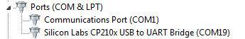
As you have plugged in the USB connector cable of the RAK8212 adapter board into your PC, a COM port should have been assigned to the serial interface. You can find out the assigned COM port using the Windows Device Manager. In my case, the COM port is COM19.
Setup a serial connection to this COM port using the terminal application “putty”.
Enter the COM port name as “Serial line”, 9600 as “Speed” and “Serial” as “Connection type”.
Press the “Open” button to start the serial terminal session.

After pressing the RESET button the the RAK8212 adapter board, you should get an output in the terminal as follows:
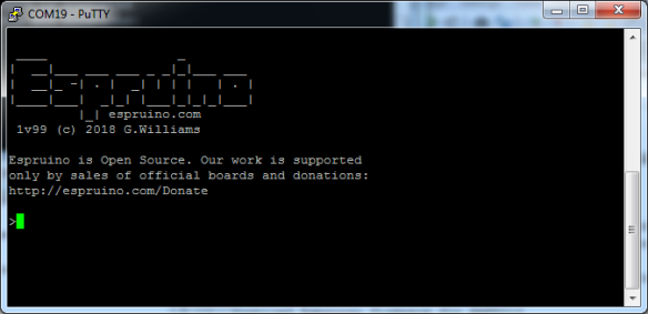
You now no longer need the J-Link adapter and can remove it from the RAK8212 adapter board.
Set up Web IDE
Download the Espruino Web IDE for the Chrome browser following the instructions here: https://www.espruino.com/Web+IDE
Run Espruino Web IDE from Chrome’s home screen (or the App Launcher).
Click the orange Connect/Disconnect icon in the Top Left.
You should be asked for the right COM port to use now. If everything goes well, the Web IDE will connect to your RAK8212.

You can now start to play with some JavaScript examples and send them down pressing the button “Send to Espruino”.

Now have fun with trying out some example programs and get familar with JavaScript programming in Espruino!

Hello There,
can you please help me to connect RAK8212 with ESPRUINO using “BLUETOOTH”?
i can successfully connect this board through com port.
but for testing AT command is it necessary to connect board using BLUETOOTH?
fisrt time i had done that thing but im not receiving anything back.
please help me with some code to start with GPS tracking.
wrire now i just wanna test this module is working with any SIM (AIrtel,vodafo ) or only hologram SIM?
>but for testing AT command is it necessary to connect board using BLUETOOTH?
As written down here: http://www.espruino.com/RAK8212
There is just one Serial port on the nRF52. If you then use GPS or GSM, the connection to D28/D29 will be moved, removing your communications (over USB). If you need to maintain communications during that time, please connect via Bluetooth instead.
If you like to do some debugging by means of printing messages on the console, this won’t work with the serial connection over USB, as this will be removed as soon as you re-configure the serial port of the nRF52 to connect to the serial port of the Quectel BG96 module (used for GPS and GSM).
> please help me with some code to start with GPS tracking.
GPS example code can be found here: http://www.espruino.com/RAK8212#gps
But I didn’t try that out yet. If you run into problems, you can also check the forum at forum.espruino.com
> i just wanna test this module is working with any SIM (AIrtel,vodafo ) or only hologram SIM?
It works also with other SIM cards like Vodafone. Definitely.
dsdsds
Thanks for your Quick reply.
ok, I got it.
now I’m uploading sensor code and AT command code given on above link “THROUGH COM PORT”.
for AT command code, I’m getting “TURNING CELL ON” then disconnect and sometimes “TURNING CELL ON” then nothing at all.!!!
(I’m using Airtel SIM)
FOR sensors code I’m getting an error like this:
 espruino.com
>
____ _
| __|___ ___ ___ _ _|_|___ ___
| __|_ -| . | _| | | | | . |
|____|___| _|_| |___|_|_|_|___|
2v00.13 (c) 2018 G.Williams
Espruino is Open Source. Our work is supported
only by sales of official boards and donations:
http://espruino.com/Donate
>{ “temp”: 0, “pressure”: 0, “humidity”: 0 }
Uncaught Error: WHO_AM_I incorrect
at line 1 col 82
… Error(“WHO_AM_I incorrect”);this.w(a.CFG_A,128);this.w(a.CF…
^
in function “b” called from line 2 col 76
…on(a,b){c.writeTo(d,[a,b])})
^
in function “connectI2C” called from line 2 col 62
…DL”).connectI2C(b,{“int”:u})}
^
in function “setMagOn” called from line 8 col 2
});
^
Uncaught ReferenceError: “m” is not defined
at line 7 col 14
console.log(m.read());
^
in function called from system
>Uncaught Error: Unexpected Manufacturer ID
at line 1 col 93
…Unexpected Manufacturer ID”);if(12289!=this.r(b.DEVICEID))th…
^
in function “a” called from line 1 col 140
…c){b.writeTo(d,[a,c>>8,c])})
^
in function “connectI2C” called from line 2 col 10
{“int”:y})}
^
in function “setOptoOn” called from line 18 col 2
});
^
{ “x”: -0.0009765625, “y”: 0.1083984375, “z”: 0.9189453125 }
>
Uncaught ReferenceError: “o” is not defined
at line 17 col 14
console.log(o.read());
^
in a function called from system
>
}}}}
I’m not a JS developer so this also can’t be helped!!
can you help me with this AT stuff??
one more thing now i’m not able to connect with BLUETOOTH. it ALWAYS get disconnected. so for GPS code i’m stuck.
For support regarding connecting to the device via Bluetooth LE, please refer to this page:
https://www.espruino.com/Quick+Start+BLE
Start reading at section “Requirements”. You need Bluetooth 4.0 !!!
For you issues with the Modem and GPS:
I already told you that it won’t work when you use the serial connection over USB. If you like to output some stuff on console, the only way to go is by connecting to the device via Bluetooth LE.
The output “Turning Cell On” is okay, it tells you that the software switches the serial interface of the microcontroller from USB to the BG96 module. So that’s the moment you get disconnected.
Regarding the issues with “Sensors”:
Do it step by step:
Step #1: Cut and paste this section:
e=require(“iTracker”).setEnvOn(true, function() {
console.log(e.getData());
});
Step #2: Cut and paste this section:
m=require(“iTracker”).setMagOn(true, function() {
console.log(m.read());
});
Step #3: Cut and paste this section:
a=require(“iTracker”).setAccelOn(true, function() {
console.log(a.read());
});
Step #4: Cut and paste this section:
o=require(“iTracker”).setOptoOn(true, function() {
console.log(o.read());
});
This sensor stuff should work with USB, has nothing to do with the BG96 module.
hello There,
yeah now I have successful Bluetooth communication with WEB+IDE, a cell is now on
but I’m not getting the version of that chip I’m getting version is Undefined.
same for other AT commands no response!!
can you please tell me what’s the issue?
Instead to use example code from the Espruino site, use this one:
https://github.com/wklenk/rak8212-espruino-nb-iot/blob/master/interfacing-the-modem.js
Also read my blog post, as it uses this code.
oh, thanks. Yeah, I uploaded that code from git hub and I’m getting output like this.
 espruino.com
>
____ _
| __|___ ___ ___ _ _|_|___ ___
| __|_ -| . | _| | | | | . |
|____|___| _|_| |___|_|_|_|___|
2v00.13 (c) 2018 G.Williams
Espruino is Open Source. Our work is supported
only by sales of official boards and donations:
http://espruino.com/Donate
>Connecting Cellular Modem …
Cellular Modem connected.
Error: undefined
>
looks like the cellular modem is connected but not receiving the output of AT command. I don’t know maybe BG96 is not responding (not enough power to energies this chip) ??
and not sending responses of AT commands to console over BLE.
or maybe this module AT firmware is corrupted !!
I’m powering the module using USB given with module. is it sufficient to energies the BG96 chip?? is there any other option to power it!
As part of the RAK8212, you should have gotten a plug with a red and black cable (battery line). You need to use it, as it powers the BG96 module.
hello @Wolfgang Klenk
now I got it. the cable is “only” power up NRF52832 BLE chip not the BG96 one. to power both the chips, to use both BLE and GPS interface we have to power it with that battery interface.
Thanks for your help.
now i want your help for “JAVASCRIPT” coding
i will be back if i got error in sending GPS data to our SERVER. ha..ha..ha.
thanks in advanced.
Hello there, for GPS i’m getting erro like this :
 espruino.com
____ _
| __|___ ___ ___ _ _|_|___ ___
| __|_ -| . | _| | | | | . |
|____|___| _|_| |___|_|_|_|___|
2v00.13 (c) 2018 G.Williams
Espruino is Open Source. Our work is supported
only by sales of official boards and donations:
http://espruino.com/Donate
>
GPS {
“error”: “ERROR: 505”
}
GPS {
“error”: “ERROR: 505”
}
AND Sometimes like this:
in function “c” called from line 1 col 15
g=void 0;c&&c();void 0===g&&0<k.length&&f.cmd.apply(f,k.shif…
^
in function called from system
GPS {
"error": "RDY"
}
GPS {
"error": "RDY"
}
sometimes the error is 516 because GPS is not 3D fixed.
is there any AT command To enable GPS like SIM808 GPS MODULE (AT+GPS=1)?
Hello
when I press the RESET button nothing appears in the terminal
can you help me