Simple LoRaWAN node connected to The Things Network (TTN) using Espruino Pico and Microchip RN2483 LoRa Technology Module. As sensor a MB1242 I2CXL-MaxSonar-EZ4 is used, that is connected via I2C. It returns the distance in centimeter as an array of 2 bytes.
The most prominent goal was to find out how to design a device and its software in order to minimize the energy consumption in order to maximize battery life.
Motivation
- In many cases, LoRaWAN nodes are deployed in remote places without a static power supply. So both hardware and software need to be designed in a way that allows battery operation.
- With battery operation, operation of at least 1 year should be technically feasible these days, given that sending sensor values only a few times per day is good enough for the given use case.
- The Espruino Pico already has some operational modes for power saving, the goal is to find out how these modes can be used.
- Also the RN2483 can be sent to sleep in order to minimize power consumption. The goal is how to find out how to send this module to sleep and wake it up again, and what implications this has to the current connection to TTN.
Last but not least …
- Be a cool guy and program a microcontroller with JavaScript.
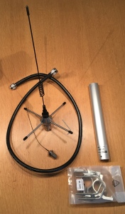
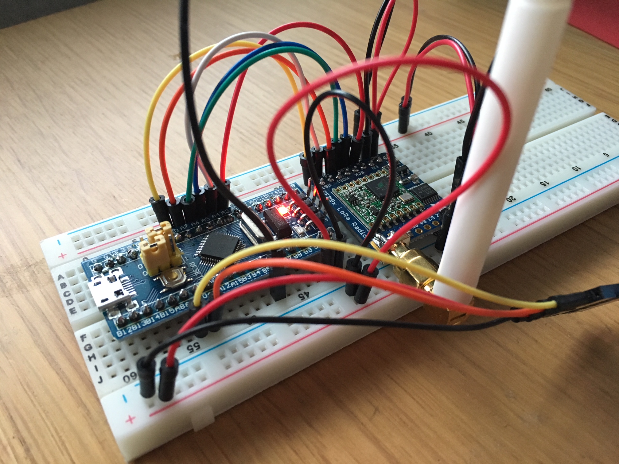
Wiring
I use a RN2483A/RN2903A breakout board that I ordered for about €30 at Tindie: https://www.tindie.com/products/DrAzzy/lorawan-rn2483rn2903-breakout-board-assembled/
Level Shifter Option: As the Espruino Pico already operates at 3.3V, there should be no need for a level shifter. However, if you like to play around with this module by simply attaching a (FTDI) Serial-to-UART cable which has 5v levels, then you probably want to have a level shifter and a voltage regulator at hand.
The Espruino Pico gets its power from a 9V battery. It has a built-in voltage regulator that converts the volate to 3.3V. Espruino Pico Pinout
The MaxBotix MB1242 consumes a consiberable amount energy, even in idle mode, so a Adafruit LM3671 3.3V Buck Converter Breakout is used as kind of “switch” to cut-off the power supply for this sensor when it is not in use. Yes, people say that cutting off the power supply is not sufficient to make sure that the MB1242 really no longer consumes any energy, but in my case this trick was very effective.

Preparation in TTN Console
Source code: https://github.com/wklenk/espruino-pico-rn2483-ttn-basic
https://console.thethingsnetwork.org/ You first need to create an application in TTN console, and create a device within this application.
Select OTAA (Over the Air Activation) as Activation Mode
After creation of the device, copy and paste the values for Device EUI, Application EUI and App Key to the code:
// LoRaWAN Over the Air Activation (OTAA)
// Copy these values from the Device Overview of the TTN console.
const deviceOTAAConfiguration = {
  'deviceEUI': '0000000000000000',
  'applicationEUI': '0000000000000000',
  'appKey': '00000000000000000000000000000000'
};
Transfer code to Espruino Pico and run it
I won’t explain here how you work in general with Espruino products, you already should be familiar with that or make yourself familiar by other means than this project.
- Connect the Espruino Pico via USB,
- use the Espruino Web IDE to transfer the code (I still use the native version for Windows)
- Run the code by entering onInit(); on the Pico
Note that the Pico won’t go into stop mode until connected to USB. You need to connect a battery (or another power source) to try that out.
https://www.espruino.com/Power+Consumption
Example output
 ____                 _
|  __|___ ___ ___ _ _|_|___ ___
|  __|_ -| . |  _| | | |   | . |
|____|___|  _|_| |___|_|_|_|___|
          espruino.com
 2v06 (c) 2019 G.Williams
>
>onInit();
=undefined
["sys get ver\r\n"
] "R"
] "N2483 1.0.5 Oct"
] " 31 2018 15:06:5"
] "2\r\n"
Version: RN2483 1.0.5 Oct 31 2018 15:06:52
["mac reset 868\r\n"
] "o"
] "k\r\n"
["mac set adr on\r\n"
] "o"
] "k\r\n"
["mac set appeui 70B3D57EXXXXXXXX\r\n"
] "o"
] "k\r\n"
["mac set deveui 00022CBFXXXXXXXX\r\n"
] "o"
] "k\r\n"
["mac set appkey 625C109CA95ADA37E9D0EA64XXXXXXXX\r\n"
] "o"
] "k\r\n"
["mac join otaa\r\n"
] "o"
] "k\r\n"
] "a"
] "ccepted\r\n"
Result: accepted
RN2483 go to sleep
["sys sleep 86400000\r\n"
RN2483 sent to sleep
Periodic task started.
RN2483 wake up
] "\u0000"
] "ok\r\n"
["\r\n"
] "inv"
] "alid_param\r\n"
wake up finished
["mac tx uncnf 1 42\r\n"
] "o"
] "k\r\n"
] "m"
] "ac_tx_ok\r\n"
RN2483 go to sleep
["sys sleep 86400000\r\n"
Periodic task done.
>
espruino.com
2v06 (c) 2019 G.Williams
>
>onInit();
=undefined
["sys get ver\r\n"
] "R"
] "N2483 1.0.5 Oct"
] " 31 2018 15:06:5"
] "2\r\n"
Version: RN2483 1.0.5 Oct 31 2018 15:06:52
["mac reset 868\r\n"
] "o"
] "k\r\n"
["mac set adr on\r\n"
] "o"
] "k\r\n"
["mac set appeui 70B3D57EXXXXXXXX\r\n"
] "o"
] "k\r\n"
["mac set deveui 00022CBFXXXXXXXX\r\n"
] "o"
] "k\r\n"
["mac set appkey 625C109CA95ADA37E9D0EA64XXXXXXXX\r\n"
] "o"
] "k\r\n"
["mac join otaa\r\n"
] "o"
] "k\r\n"
] "a"
] "ccepted\r\n"
Result: accepted
RN2483 go to sleep
["sys sleep 86400000\r\n"
RN2483 sent to sleep
Periodic task started.
RN2483 wake up
] "\u0000"
] "ok\r\n"
["\r\n"
] "inv"
] "alid_param\r\n"
wake up finished
["mac tx uncnf 1 42\r\n"
] "o"
] "k\r\n"
] "m"
] "ac_tx_ok\r\n"
RN2483 go to sleep
["sys sleep 86400000\r\n"
Periodic task done.
>
Results
- The experiment up to now runs for more than 6 weeks now, longer than any battery powered circuit I did before. Update 2020-12-29: Died after 45 days, which is a little disappointing.
- Maybe it could be even more power-efficient if we could eliminate the voltage regulator on the Espruino Pico and use an appropriate battery instead
- The Microchip RN2483 module has quite helpful in keeping the complexity of the LoRaWAN protocol away from the project, especially suprised with its duty cycle enforcing mechanisms and adaptive data rate functionality. It also has a nice functionality to send it to sleep and wake it up when needed again. https://www.thethingsnetwork.org/docs/lorawan/duty-cycle.html
To visualize the measurements, I used
- Node-RED
- Application Nodes for “The Things Network”
- Node-RED nodes to save and query data from an influxdb time series database
- InfluxDB
- Grafana
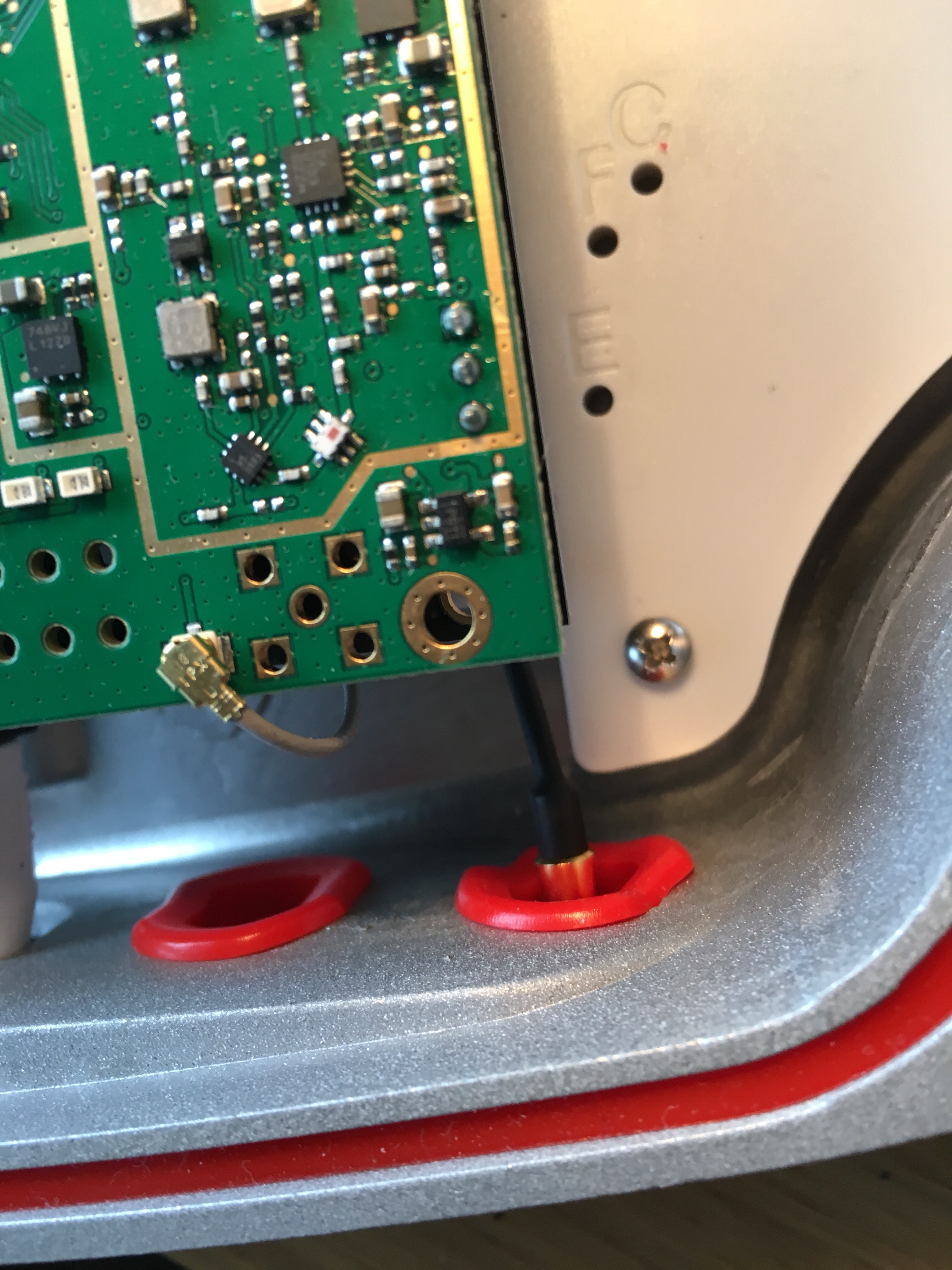
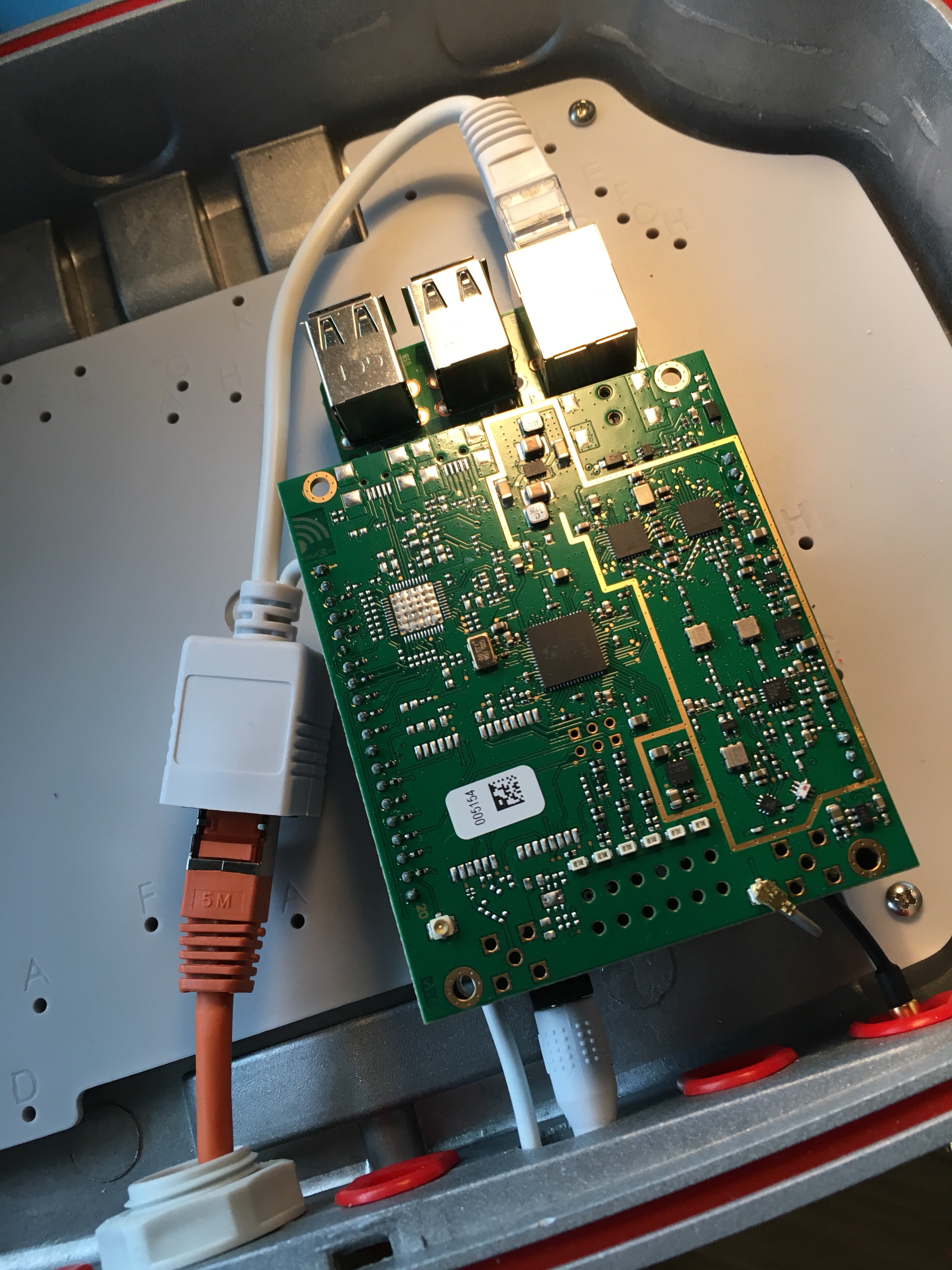
Running now for more then 6 weeks, hanging on the ceiling of my garage

Sending a distance value every 30 minutes (well, there are some few losses)

Some similar project with focus on energy consumption and also using an ultrasonic sensor can be found here:
https://www.hackster.io/Amedee/low-power-water-level-sensor-for-lorawan-the-things-network-96c877